Model 28 TTY project...
|
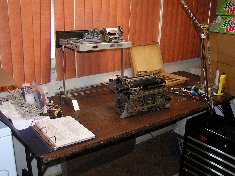 |
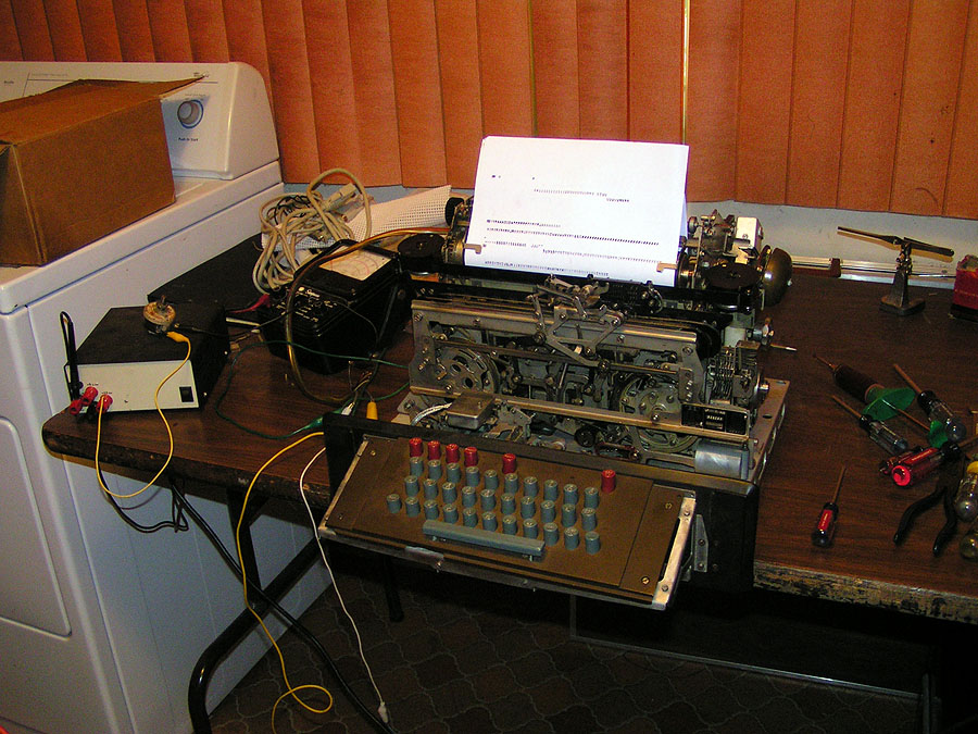
| After a bit of a cleanup - the work area is ready for the next phase - the alignment / adjustment / lubrication of the Automatic Typer, or page printer as some call it. |
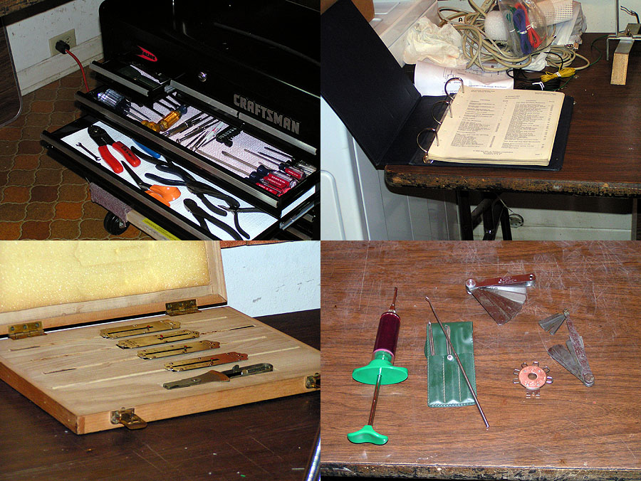 |
| Tools at the ready. We have several tool boxes - ranging from small handy tool boxes that I carry to jobs (including several "specialized" ones - such as "the cable kit" which has parts and tools for making up, testing and installing serial, ethernet, telephone and alarm system cables); to a monster Craftsman tool chest that is as tall as I am and weighs nearly a half ton - (I found out about it's weight the hard way when I moved it from California after my dad died). Sherry even has a double-decker that she keeps here leather and other craft tools in. The problem is they are so and big - you wind up walking over to them (or at least standing up) to reach stuff. The tools I used for working "at the bench" were stored in two places - the smaller ones in a small drawer "in the bench" itself - and medium sized tool box that sat in the floor - never within reach when I needed something. (if you don't know about "the bench" - you can see it here: The Bench . In the first picture on that page - you can see the small drawer in the front of the bench - the tool box is just out of the picture below and to the left of the URA-8/ CV-89A sitting in the floor next to the bench). Back to toolboxes - recently - I got an email from sears noting this huge sale on tool boxes - mostly they were touting their $1000 "gee-Whiz - What Is That Thing" tool chest (you may have seen it - looks like something out of StarWars - or StarTrek or something - called the AXS system or some such) - but I also noted that their mid-line chests were on sale for almost 1/2 off - including some of the ones with Quiet Glide slides - which I prefer. The best thing was finding a low cart to put it on which has it at a perfect height to reach "stuff" while seated. This gives me a convenient place to store AND use precision tools like used for working on electronics and - of course - Greenkeys... Oh - and the thing is short enough that it rolls right under the table when not in use. Of course being "me" I couldn't leave it alone - the first thing I did when I got it home was modify it - though in this case it's simple and fully reversible: I pulled the locking bar "pins" out of the locking bars - and removed them - that allows me to open the drawers without having to open the top lid. Neat thing about the way it's built, though - you can still lock the top center drawer with the key.
The one bad thing is - the wood box the spring scales came in is too deep to fit in a drawer - so I'll have to find some place else for them - fortunately - I shouldn't have to use them all that often. I can tell you now, though - they just paid for themselves - on this project alone! More on that in a bit. The other "specialty" tools - like the spring gauges, micrometer, calipers, spring hooks and feeler gauges all have a nice safe place, now - with the bonus of being real handy! One other "note" here - most people are probably familiar with the "four screw-stud" binders that teletype manuals use... I wonder how many know that the pages are also "punched" to fit a three-ring binder? That makes it real handy to use a "section" of those often huge (and unwieldy) manuals- pull out the section you need (in this case it's the 150 page section on the Automatic Typer Adjustments) - and put it in a spare notebook. I use a big "D" ring job - it's easier on the holes in the pages since the "D" is so big; the thing opens flat and doesn't keep trying to "close up"; and obviously that make seeing both sides of the pages easier since they lay flat. |
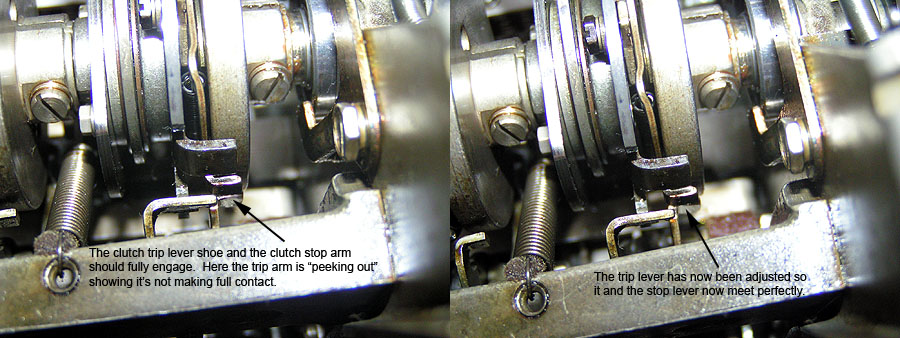 |
| Most of the adjustments were pretty much dead on - save of course for the ones I "messed" with when I pulled the main shaft out to change out the gears. Even so - most were still close enough to work - just not as well as they could be. The picture here shows the slight misalignment of a clutch trip/stop link. Most adjustments were like this. The worst was the eccentric stud on the rocker shaft bracket that sets the rocker shaft position from the drive link on from the type box clutch ( which I had loosened - though I'm not entirely sure why). Anyway - nothing out of the ordinary was found - most springs were well with-in specs (unlike the keyboard - which I'm sure has at least two springs that need replacing). |
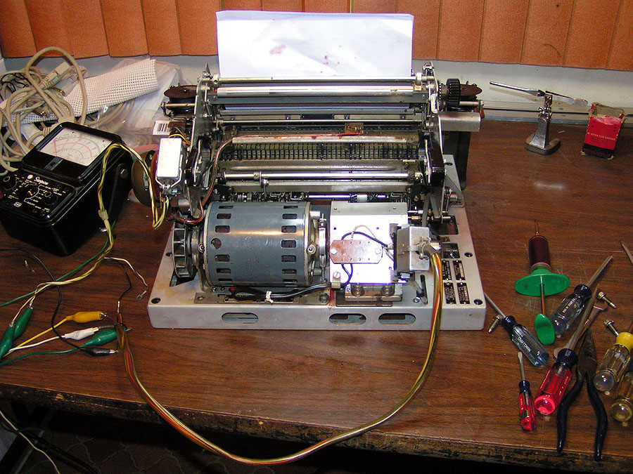 |
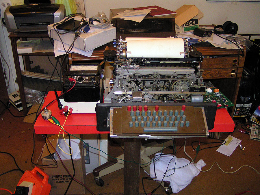
| With the adjustments done, the Automatic Typer was again mounted. The motor was hand-rotated and everything checked. I'd been using a jewelers screw-driver "jammed" into the selector magnet to hold up the armature - but once I started into working on that part of the adjustments - I felt it was better to "operate" the selector armature the way it should be done - I.e. 60ma. DC. I found that 12V though about 150 ohms would give me right about 60ma.; and indeed the armature slapped right up. So the next hour and change was spent fine-tuning the adjustments in both distance and force. When I got through - I could hand turn the motor, press the "R" key - and the typer would (eventually) type an "R". And a "Y". Well truth be told - at first I got characters shifted over one bit - I'd left the Ranging Control at one end - and when I got my head out of my - well - got the ranging control back to 60 - then indeed I got "R"s and "Y"s. So - powered it up. YIKES! the gear noise was way too loud! - Something is NOT happy! Powered, down - checking all of the back-lash - the only thing noted was that there was barely - just barely any back-lash between the drive gear in the transmission - and the driven gear on the main shaft. In fact the back lash between the drive gear and the gear that drives it (in the transmission) was WAY more than the other. So - next step is to figure out what isn't happy. The transmission mount nuts are pulled - so there is just a "little" give - and the motor run back up. By pulling, pushing, etc. - it became obvious it was the mesh of the transmission drive gear and the main shaft driven gear... apparently "just barely perceptible" mean more than what I had allowed. So the motor is pulled, the transmission off it's mounts - and the screws to the transmission mount loosened. Transmission back in place motor in place with one screw just so it can't crawl up and off the input gear - there is a LOT of torque right there... and I'll be holding the transmission itself. Power back to the motor - and pull back slightly on the transmission... a bit quieter... so back just a bit more - nearly silence (at least compared to the "growl" from before). Making ever so slight adjustments in - out rotate slightly (to check for the gears meshing square - and not at some angle) - and finally the best position is found. While holding the transmission with something like a death grip, the motor is powered down, a small Phillips is run down to the two back screws and they are tightened as much as that small screw driver can do... the transmission is then pulled - all the mount screws tightened with appropriate sized tools, then the transmission is installed - and the motor. The motor pinion to transmission gear mesh is checked - sure enough it's now also a bit tight - and appears to be at a slight angle. The height / leveler adjusters on the rear transmission frame are tweaked until the mesh is right - and now the two gears are parallel - mesh side to side is the same. The final hardware re-installed and tightened - the motor powered and everything checked. Now the gears are happy. Two and a half hours. While not a total surprise - since this was a MAJOR modification to the chassis, etc. - still this was the single longest and hardest "adjustment" of the entire project. What I figure is the problem - I've mixed a nylon (or whatever synthetic it is) gear with one of the older fibre gears - and the teeth "depth" is different - so even when there was still a bit of back-lash between them - apparently the teeth of one gear (I thing the nylon gear from some "looking" at other teletype gears I have here) was "bottoming" against the bottom of the "groove" of the fibre gear... Remember - the Automatic Typer had a nylon driven gear originally - but I replaced it with a "set" of fibre gears (the "set" included a drive gear for the keyboard) - and apparently- even though they have the same "pitch", etc. - the teeth depth appear slightly deeper on the nylons than the fibre gears... and that was causing a lot of noise. |
 |
| OK - Progress. Gee - I've got "lock-up" at 60ma. - even though I don't have anywhere near the usually applied 90 or more volts - what happens if I press a key? Well it types - but the wrong character - that's not surprising. But at least it's doing something. Peck a few more characters. Dang - that bail back there sometimes rotates too far - knocking the non-repeat lever out of it's guide - which keeps the trip lever from resetting (and re-setting the bail). Small screw-driver - slip the non-repeat lever back into it's guide - cycle the clutch - there - the keyboard is working again. I thought I had this fixed - it's part of that "issue" I had before - and it works OK at hand-turned speeds - but under power - it acts-up every few characters. I'll get to that later - now I have spring gauges to check the trip lever spring - which I suspect to be too weak to do it's job. Well this little power supply can do 24V if I connect from the -12 to the +12 output. Turn my current pot to 1K -- move the leads - turn on the supply - set to 60ma. Power the motor - instant lock up. Type some characters - Hey - they are consistent - wrong - but consistent. Type a few more (dang! there goes that lever again!). Type. OK - by the book Bit three is middle bit - should give me a space - hmmm Carriage return. Well Line Feed is Two - Hey Space - I'm off a bit (Hitting Head!) Idiot - you left the ranging control at one end - (dial dial to 60) R "R" Y (nothing - crap that lever is out again) recycle - Y "Y" R "R" Y "Y" A "A" B (nothing - lever again!). But hey - the dang thing is tracking it's own character generator at 60 WPM on 24 Volts!!! I wonder - what's the chance one of those BlackBox CL050 could key this thing? after all - they are rated 30V external... Hmmm... OK - sidenote. During the week - I'd had a little time - and I'd used it to reverse engineer one of the Blackbox CL050 units I got from ebay. Black Box rates them at 30V - but actually - that's conservative as the lowest rated component in the circuit is rated 50V max (of course I'd be conservative too considering the environment these can be found in). They have diode snubber and polarity protection - and with a few parts (4) I think I've come up with a "modification" that will allow them to handle loops up to 130V (passive mode only, of course). I have some testing to do - as the circuit allows a "leakage" of around 3ma. I don't think that'll effect most machines - but as noted - I've got some testing to do. However - being familiar with the circuit in the transmit loop -- I know voltage drop is minimal - and should be blazing fast (that makes sense considering the upper baud rates they can run). Point being - if I've gotten the selector in this thing so happy that it'll read it's own keyboard at 60WPM with only 24V driving the 60ma loop -- it likely won't know the difference if the drive is coming from a CL050. |
 |
| So every thing get's moved to the Office - where the computer is already set up with the needed software and ready serial port. |
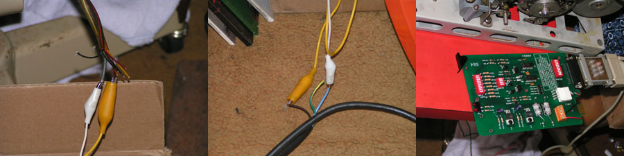 |
| The LESU is a bit - ah - primitive - (yikes - hope the local fire marshal doesn't see this! Although you'll note the extension "reel" everything is plugged into - is fused). Check the configuration of the CL050 with a "port sniffer" - (that's the RS-232 line monitor doohickey at the right of the right-hand picture) - yup - backwards - fortunately - the CL050 has a set of switches to change from DCE to DTE - flip-flip-flip... OK - it and the computer are happy with each other...
As they say - the proof is in the pudding... |
Click Here for a video of the first computer driven run of the Model 28 "kit"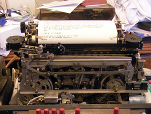 |
|
|
| I guess I wasn't that surprised that it worked - after all - quite a bit of testing, etc. - had proceeded this test. What was a surprise that it also copies fine at 100wpm (though it needs a bit of an adjustment as the R alignment drifts a tad - often to the right jamming the Y). Regular copy looks OK - though it looks GREAT at 60WPM - which is where it'll spend the greatest amount of time.
Needles to say I'm pleased - while there is much yet to be done (list follows) - it's always nice to have "that sound" and "that smell" back in the house. I'm going to take a moment and thank some people: First and foremost: Riceguy - at who's feet I lay the blame for this project - along with many, many thanks! He was the one that suggested this a possible project - and backed it up with a ton of parts, support and good suggestions. Second is George Hutchison - without the service information, etc. he provided - I'd be stumbling along - probably looking for parts to replace the ones I broke not getting things right. And also Don House for some excellent advice. I didn't always follow it (wish I'd known about the dowel trick with the main shaft BEFORE I pulled this one) - but his advice has been helpful in several areas. And last are the many members of Greenkeys - I'm not going to start naming names here - because sure as I do - I'll miss someone - and with all the kind words of encouragement, helpful advice, etc. - I sure don't want to slight anyone even by accident. Thanks one and all! OK - I have a running machine. ToDo: 1) get the issues with the keyboard fixed. Shouldn't be difficult now that I have the right tools. 2) Figure out what to do with the transmission "shifter". Right now the shift "collar" is just spinning loose. Yeah I can reach back and shift it -- but there is no outer stop. One pull too long - and I get to reassemble the shift mechanism - that is if it's not damaged in the process. 3) Cabinet. Yeah - I saw the table-top on ebay. I'd give $200 for that cabinet shipped to my door (and they can keep the keyboarders). Guess I'll wind up paying at least half that to get a regular cabinet shipped in. Hopefully it'll come with a proper LESU. Riceguy is trying to talk me into making a "clear" (as in Lucite, etc.) cabinet to "show off" the 28. I'll admit - while the "idea" is tempting - I have absolutely no experience in fabricating such in plastic. I'm not even that good at polishing plastic, much less forming it into something that intricate (think see-thru table-top cabinet). 4) I think I've figured out what else is missing on this unit - I *think* the 28 we had before had a local LTRS shift key / mechanism. Have to look into that. I know the Kleinschmidts had it - it's only been 20 years since we sold the 28 - and memory ain't what it used to be, and I may be mixing that up!. 5) Speaking of local - there wasn't any way to put the local auto shut-off timer mechanism in this unit - and FIGS H prints # as does most "A" code typers. Our old one did a shut-off on FIGS H - so I think I'l try and figure out how to install that on this one. There are some "apparent" extra function bars - there are three right next to the one for the bell switch - but I've yet to see them activated (the one for the bell "kicks" when FIGS S comes in - but the bell isn't "powered" yet - so it doesn't yet ring). 6) As noted - the bell. I'll probably wait and see what happens with a cabinet / LESU - as the bell is usually installed "there". 7) This and the next half-dozen for the suggestions sure to come.... |
|
|
|
|
| Site contents copyright © 2008 Randy Guttery |
|
|